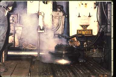
Not all interfering environmental effects stem from target offgas. Fig. 3 shows a weld seam almost completely obscured by steam.
Figure 3
In this pipe mill steam almost obscures the weld seam – the temperature measurement target. The pipe seam produced by the welder (Thermatool) is located just to the left of the vertical cylinder in the center foreground. Radiation pyrometer measurements must also contend with dust, smoke, flame, and target offgas.
IMMUNITY TO NOISE
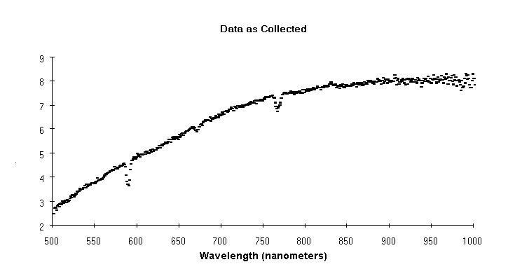
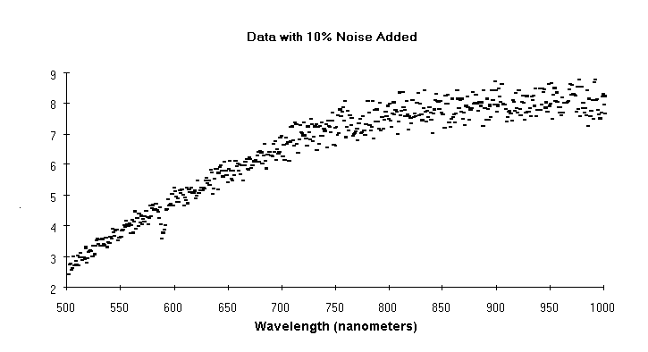
A noisy signal, distorted by optical or electrical interference, can also cause problems. Andreic reports that noise of as little as 1% can render multi-wavelength techniques unsuitable due to the large error that results. He observed a 5% error resulting from 1% noise. The following example shows that noise of 10% has a small effect on the new measuring technique. Fig. 4 represents the data collected in an industrial environment, complete with small absorptions at 588 and 765 nanometers; Figure 5 shows the same data with 10% noise added. The temperature calculated for the original data was 2887.0 ±10.3°C; after the noise addition the calculated temperature was 2899.7 ±23.2°C. The error resulting from the 10% added noise is 0.4%. Interestingly, the tolerance has increased 12.9°C, accurately predicting the 12.7°C change in indicated temperature.

Figure 4
Data collected in an industrial environment. Temperature calculated was 2887.0 ±10.3°C. Noise is added to these data to create Figure 5.

Figure 5
The same data as in Figure 4 with 10% noise added. The temperature determined is 2899.7 ±23.2°C. The error resulting from the noise addition is 0.4%. It was accurately predicted by the increase in the tolerance from 10.3 to 23.2°C. Others have reported error of 5% resulting from 1% noise.
ADAPTABILITY/BROAD TEMPERATURE RESPONSE IN ONE ELECTRONIC UNIT
The unusual way of calibrating makes it easy to adapt various optics to the pyrometer. Everything from bare fiberoptic cable to commercial camera lenses has been used to get a view of the intended target. The different optical pickups can even be fitted in the field if desirable. The adaptability of the methodology can be shown by a list of some successful applications. These applications, Table 1, used the basic electronic unit with a variety of optical inputs:
Table 1Variety of Successful Applications of New Multi-Wavelength Pyrometer
- ceramic manufacturing
- glass processing
- fiber drawing
- chemical vapor deposition and infiltration
- carbon and carbon/carbon manufacture and testing
- combustion<
- ultra-high temperatures (>3300°C/6000°F)
- exotic metal alloys (oxides vary with thermal history)
- reflective environments (temperature gradients inside heated objects)
The temperatures measured in these applications ranged from 500 – 3500°C. This does not represent the upper limit of temperature; as we mentioned earlier, high temperature response is essentially unlimited.
SUMMARY
A new multi-wavelength pyrometer has been used to solve formerly intractable problems. Unknown or changing emissivities and environmental interferences have been readily overcome. The new instrument, which is suitable for temperatures ranging from 500 to beyond 3500°C (900 – >6300°F), is capable of exceptional accuracy to within 0.1%. It requires no prior knowledge of either the target or the environment. It provides a tolerance for each temperature measured so the operator knows that the measurement was successful. In some cases standard instrumentation can be used after the new pyrometer measures the emissivity and locates the environmental interferences. In our experience problems of long standing can be resolved rapidly when the new instrument is used.

